Do not measure the collet or cutter
A dust boot mount clamps to the stationary outside body. The collet nut, tool shank, cutter, spindle nose, and motor power are different specifications. Even a product sold as a “2.2 kW spindle” can use a body that differs from another spindle with the same power rating.
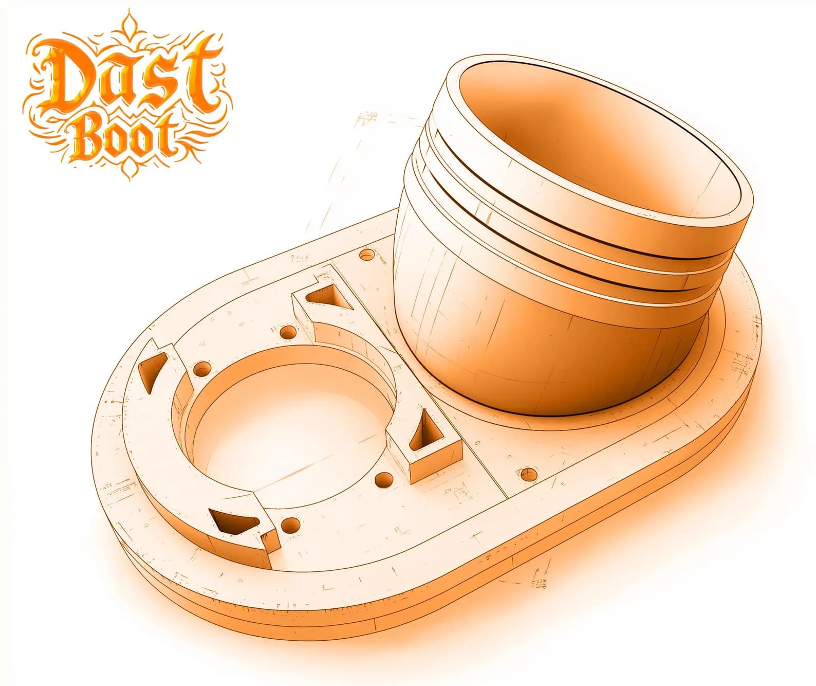
1. Find the mounting plane
Look for a straight, uninterrupted section of the body that:
- matches the intended clamping diameter for enough vertical length;
- does not cover cooling vents, controls, connectors, or lubrication fittings;
- sits low enough for the skirt to reach the work without sacrificing safe travel;
- leaves access to the collet when the magnetic skirt is removed.
2. Measure circular bodies
- Power down and unplug the spindle or router.
- Clean dust from the intended clamping surface.
- Close the calipers lightly around the body without compressing plastic housings.
- Measure again after rotating the calipers 90 degrees to catch an oval or interrupted body.
- Record the result in millimetres; do not round a 62 mm body to 65 mm.
3. Measure square bodies
Record both dimensions at the mounting plane and note corner radii, bolt heads, or rails. Dast Boot’s square catalog option is 80 × 73 mm. A body with the same nominal width but a different length is a different fit.
4. Measure the machine envelope
Check plates, bearings, rails, and the lowest carriage features.
Leave wrench, collet, and cutter access with the skirt detached.
Include clamps, screws, vacuum fixtures, and the tallest stock.
Allow bend radius, support, slack, and movement at the top of Z.
5. Run a powered-off clearance check
After installation, keep spindle and extraction power off. Jog or move the machine slowly through the intended X, Y, and Z envelope. Repeat the check with the actual stock, workholding, cutter length, and hose routing for the job.
Aftermarket Z carriages, spindle upgrades, lasers, tool setters, hose supports, and clamps can all change the available space.